
‹
›
‹
›
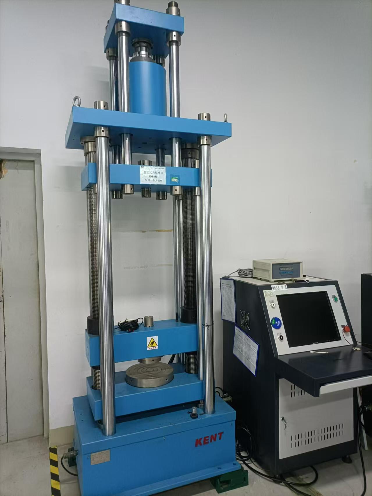
Deadweight Force Standard Machine
1.Product Overview
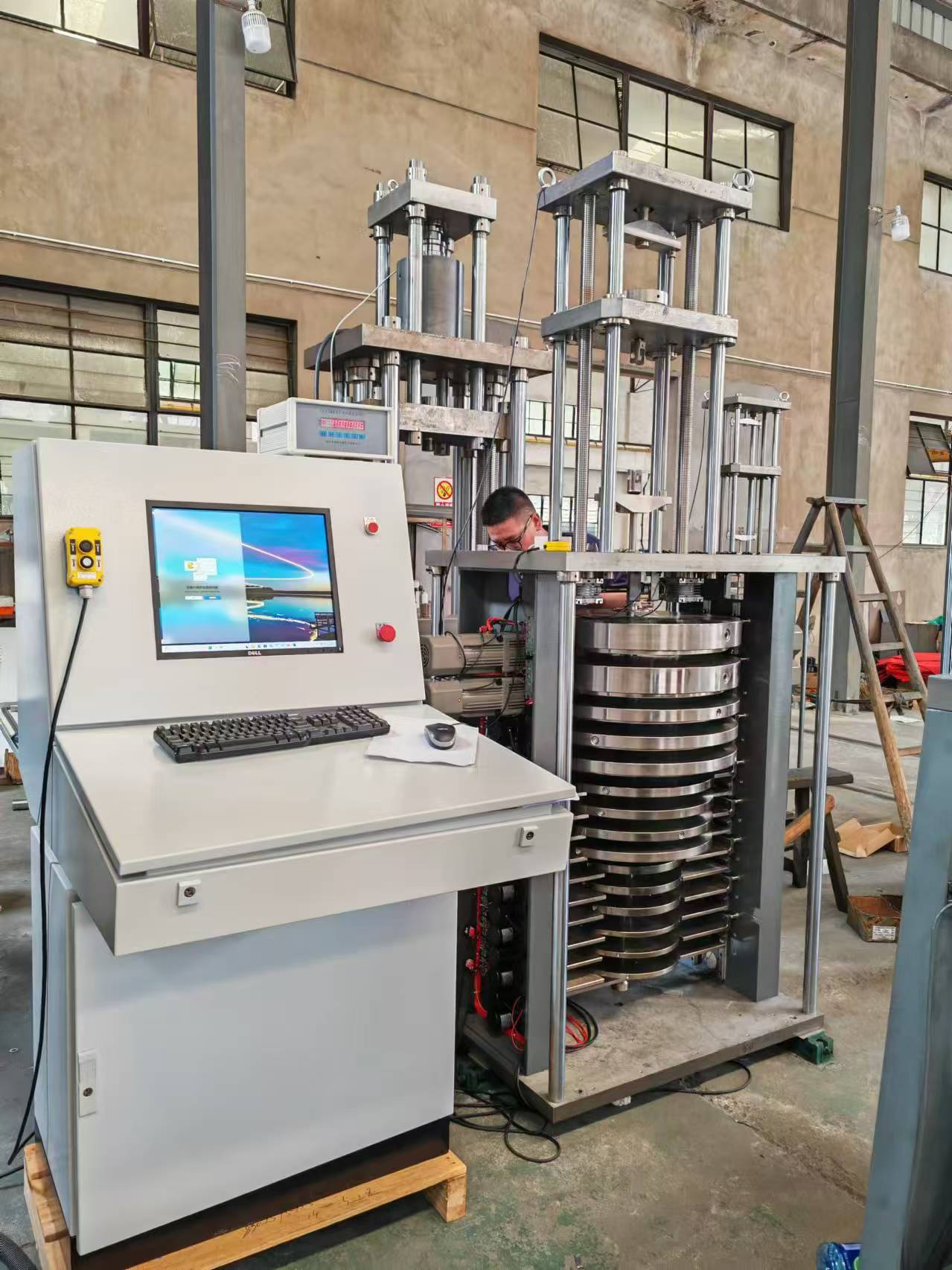
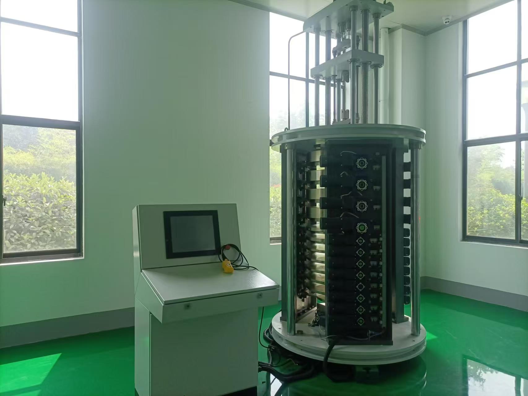
The deadweight force standard machine equipment includes a load-bearing frame, a force-receiving frame, a weight set, a weight drive mechanism, a workbench, automatic control software, and a printer, etc.
The bidding equipment fully meets the requirements of the Verification Regulation for Force Transducers (JJG391-2009), the Verification Regulation for Load Cells (JJG669-2003), the Verification Regulation for Working Force Measuring Instruments (JJG455-2000), and the Verification Regulation for Standard Force Measuring Instruments (JJG144-2007), enabling the testing, calibration, and verification of sensors.
2.Technical specifications and parameters
3.Detailed technical description: Deadweight force standard machine
3.1Basic characteristics
The electric independent weight-adding and static weight-type force standard machine, which means each weight has an independent mechanism for adding and removing, allows all weights to be added or removed independently or simultaneously. It integrates the advantages of similar technical devices existing in the world and is designed and manufactured using advanced technical means and methods.
On the premise of meeting functional and basic performance index requirements, compared with traditional similar technical devices, innovations have been made in terms of weight loading and unloading methods, overall structure, and automatic control, featuring the following technical characteristics:
1) Electric independent incremental working mode
Electric independent weight addition is achieved by synchronously moving the weight carriers up and down using a motor drive. Each weight carrier can be driven independently, and each weight can operate independently. Arbitrary independent, combined, and full driving of weights is possible, simplifying the weight driving mechanism, greatly simplifying the structure, and reducing the failure rate of the weight driving device. The weights can be arbitrarily combined, increasing the degree of freedom in weight loading and unloading, and broadening the measurement range of the entire machine.
2) The loading and unloading of weights is smooth and reliable
The weight drive device utilizes a high-performance motor as the prime mover and a simple yet highly reliable cam mechanism as the actuator, ensuring a smoother and more reliable process for loading and unloading the weights.
3) Modular host structure design, reliable operation
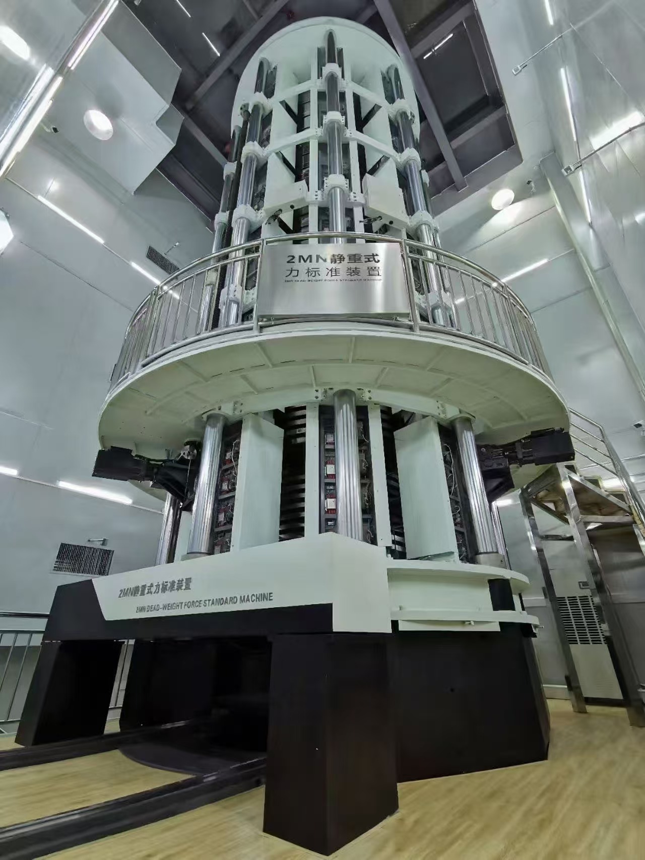
The main structure is supported by a unique combination of columns and welded frames, with upper, middle, and lower beams integrated with the support columns. The beam in the middle of the frame divides the equipment into an upper working space and a lower space for hanging weights.
The overall design is simple and aesthetically pleasing, boasting high rigidity and ample space, making it highly suitable for sensor testing. All functional components are designed using mature modular components, seamlessly integrated with lean manufacturing. The comprehensive software and monitoring functions effectively complement each other, ensuring reliable operation and minimal maintenance of the equipment.
4) Automated work process
Utilize microcomputer control technology and automatic detection technology to solve the problem of stable motion control for large masses, achieving automatic precise loading and unloading control and weight exchange control. The working process is automated, visualized, and monitorable. Process control, data processing, and management are carried out in accordance with international standards, national standards, and other special requirements.
5) Fully meet the functions and specifications of sensor testing
In accordance with the requirements of international standards, national standards, and verification procedures for the calibration, verification, and evaluation of force sensors, testing of force sensors within the measurement range is achieved through optimizing the design of mechanical structures, weight configuration, control processes, and software development.
6) Easy to use, simple to operate, safe and reliable
Microcomputer control, software visual interface operation, simple training is all that's needed to refer to the instructions for self-operation. There are no unreliable links during work, and no safety hazards.
In summary, the electric independent incremental deadweight force standard machine in this bid is a novel, progressive, reliable, and practical device with outstanding performance compared to similar devices worldwide.
3.2Basic Principles
The basic working principle and structure of the deadweight force standard machine are implemented with reference to the deadweight force standard machine. Based on the dynamic effect of force, the reference force value is reproduced directly by using the gravity of a known mass weight. According to Newton's second law, and considering the influence of air buoyancy, the gravity f of a weight with mass m in the air is 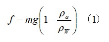
In the formula, g represents the gravitational acceleration at the location of the weight.
The gravitational force of the weight is applied to the sensor under inspection through the central suspension rod and the pull head, as shown in Figure 2. According to formula (1), as long as the mass of the hung weight is known, the load acting on the sensor under inspection can be calculated.
According to the detection requirements of different sensors, applying weights with different gravitational forces to the tested sensor according to certain rules can achieve performance evaluation of the tested sensor. Since the mass of the weights can be calibrated by high-precision scales and high-precision comparators, and even by force calibration of a single weight, and gravitational acceleration and density are constants, the mechanical structure of the device, the way of loading and unloading weights, and the control process must be reasonable. In this way, the equipment can achieve high performance and convenient operation.
3.3 Mainframe structure of deadweight force standard machine
Loading structure method: Reverse frame - central suspender - weight hanging method based on fundamental principles
Overall layout: Upper part - crossbeam working components; lower part - mainframe frame, weights, and drive components; central part - hanging components.
1) Upper part of the device
It comprises an upper crossbeam, a column, a welded frame, a moving crossbeam, and a driving mechanism.
2) Upper crossbeam
The steel plate is designed with a maximum bearing capacity of three times the design load, and is processed after aging.
3) column
The structure of 2 lead screws and 2 guide pillars is adopted, and the synchronization issue is considered during processing.
4) Host framework
Taking into account the rigidity, strength, and stability of the overall framework, additional welded frames are incorporated to ensure high-performance testing results.
5) Moving beam and driving structure
Utilizing high-precision lead screws, screw inserts, and timing belts, driven by a motor with adjustable speed, or manually raised and lowered through preset operation control buttons, ensures the synchronization of both sides of the moving crossbeam as it moves up and down.
6) Lower part of the device
Including the mainframe, weights, weight loading and unloading mechanism, hanging anti-sway and detection mechanism, etc.
7) arrange
The inverted tower shape with a large top and a small bottom is adopted, and its main advantage is that the center of gravity is higher, resulting in a shorter swing period when adding or removing weights.
8) support structure
The column is equipped with a welded frame, evenly distributed on both sides.
9) Weight loading and unloading mechanism
Electric independent weight addition is achieved by using synchronous motors to drive the weight carrier up and down. Each weight carrier is driven independently, greatly simplifying the structure of the device. The weights can be combined freely, expanding the degree of freedom in loading.
10) Hanging anti-sway and detection device
Reduce or eliminate the low-frequency shaking that may be caused by adding or removing weights on the hanging system, while simultaneously detecting the actual shaking amplitude.
Among the existing machines, the 1MN deadweight force standard machine from the National Institute of Metrology, China, the 1MN deadweight force standard machine from PTB in Germany, and the 500kN deadweight force standard machine from AVIC Electrical Measurement have adopted suspension anti-sway and monitoring devices.
The loading and unloading of weights is achieved through an electric independent weight-adding method. It involves an electric motor driving a crank slider to perform up-and-down linear motion. The motion displacement follows a harmonic pattern, ensuring smooth motion at the start of weight-adding and at the end of weight-unloading, theoretically eliminating impact. However, since the initial position of the hanging tray is near the midpoint of the bracket's motion stroke and it has a high speed, harmful impact phenomena may occur at the moment of contact and disengagement between the weight and the hanging tray. Therefore, measures must be taken to reduce this impact, specifically by designing a vibration-reducing body to decrease vibration intensity and mitigate the disturbance of impact force on the equipment.
For this reason, shock pads are installed on each bracket. Additionally, it is noted that the absolute speed of the weight lifting and lowering is very low, so there will be no significant impact vibration.
Due to various factors such as the geometric dimensions of equipment installation and motion stability, when weights are placed on or removed from the hanger, the hanger will undergo free oscillation. Therefore, an active anti-oscillation control measure is adopted. As shown in the figure below, this is a crank-slider mechanism driven by an electric motor, where the slider moves up and down linearly along the guide rail. The right end of the slider is equipped with a central hole. When the slider moves up and down, it can achieve contact or disengagement between the inner wall of the hole and the outer circumferential surface of the anti-oscillation tray on the hanger rod. In the contact state, the end of the hanger rod can be prevented from oscillating.
11) central location
The central part of the equipment is equipped with a hanging rod and a weight tray, as shown in Figure 3. Considering the requirements for strength, corrosion resistance, and wear resistance, the materials for the hanging rod and the tray that bears the weights are selected from alloy structural steel. After heat treatment, the surface is plated with hard chromium to enhance strength, corrosion resistance, and wear resistance.
4. Weight configuration combination
The nominal values and combination methods of the weight masses are determined based on the requirements of the bidding documents and by referencing the weight configurations of similar equipment both domestically and internationally. The detection requirements of the bidder can be met without exchanging weights. The specific configuration is as follows:
Hanger, reaction frame 100N+100N, weights: 100N*4, 200N*4, 400N*3, 600N*1, 1kN*3, 2kN*2, totaling 17 levels of weights, with a total weight of 10kN. It meets the five-point testing requirements for sensors of 500N, 1kN, 2kN, 3kN, 5kN, and 10kN.
4.1 Weight material:
Q345 hot-rolled low carbon steel plate.
Disc-shaped weights are most commonly used in deadweight force standard machines. Their advantage lies in the ease of processing and manufacturing, as well as the ease of ensuring the position of the center of mass. The surface of carbon steel is treated with chromium plating for rust and corrosion resistance.
The contact area is made of alloy steel and has undergone wear-resistant treatment.
5. Electrical control system
The electrical control system for equipment design comprises an industrial microcomputer system, dedicated control cards and interface boards, motors and their control systems, supporting low-voltage electrical devices, and application software.
Utilizing centralized microcomputer control management and a combination of microcomputers and control cards, we employ advanced microcomputer software technology to achieve full automation through the design and development of complex microcomputer programs. The system composition diagram is as follows:
6. application software
6.1 software design
Utilizing the Win7/Win8.1 Microsoft operating system software platform, we employ object-oriented programming provided by advanced computer languages. The development interface is based on a single-document format, which is concise and clear. We utilize threads for serial communication to prevent the program from crashing due to serial communication wiring failures.
In the software system, various parts that need to be monitored are displayed on the interface using graphical elements (icons) with similar shapes, thus forming an animated model on the screen that can visually, vividly, and comprehensively express the mechanical structure of the equipment. Software technology is used to integrate bidirectional information between the control computer and the monitored equipment, establish a connection between the working components of the equipment that need to be monitored and the animated components on the screen, and achieve the function of representing the working state in an animated form and issuing control instructions by clicking on the animated components with the mouse.
The software runs on the control computer, featuring simple and convenient operation, as well as practicality and reliability.
6.2 Software features
Human-machine dialogue, with multiple control modes to choose from
1) Manual working mode
Realize the metrological verification of equipment and manual operation control of the position and lifting of weights.
2) Semi-automatic working mode
It can automatically operate through inputting load and parameter settings.
3) Automatic working mode
It can automatically complete pre-compression, verification, data acquisition, and processing based on the input sensor's range, number of pre-compression cycles, number of loading points, and delay time (holding time at loading points). The data processing follows the calculation principles outlined in the verification regulation of "JJG391-2009 Force Transducers", providing the sensor's accuracy level, sensitivity, linearity, hysteresis, zero output, repeatability, and long-term stability.
7. Safety protection function
7.1 The operation console is equipped with an emergency button, which allows for immediate termination and unloading of the weights to the initial position in case of abnormal conditions. When the actual loading value of the force-measuring machine exceeds the full range of the verified sensor, the software automatically protects itself and triggers an alarm to stop the test;
7.2 When the weight reaches the upper or lower limit, the test should automatically stop and the software should send an alarm signal.
7.3 Monitor each executing mechanism. If any abnormal action occurs in the loading mechanism, it should be able to automatically detect and trigger the cessation of the test, while simultaneously issuing a software alarm signal.
8. Parameter setting and real-time display
The software has functions such as monitoring, scanning, and recording the operating status, and it displays the number and position of loaded weights in real time. The software also features real-time pause, one-click reset, and automatic unloading functions. The parameter settings are simple and convenient, and the number of pre-presses, the number of loading points, the weight combination for each loading point, and the delay time can be modified according to user needs.
9. Data Management
The software automatically generates data and saves it in the database, with an output in EXCEL format for easy calling and viewing. It features a secondary saving function for computers, and the default saved file name can be set to the sensor number.
10. data communication
The data communication utilizes an RS232 interface and is designed to be open-ended, facilitating user replacement of responsive instruments in the future. The data tables and certificate covers are designed according to national standard versions and are capable of being revised in the future.
11. Technical specifications of weights
11.1 The maximum allowable error of the weight should not exceed 0.005%;
11.2 The weight adjustment chamber is arranged circumferentially at three points to ensure adjustable center of gravity;
11.3 The surface roughness of the weight is no more than 3.2μm, and it is chrome-plated with a firm and reliable coating, featuring long-term anti-corrosion properties. The surface exhibits no obvious mottling or peeling;
12. Weight drive device
12.1 Weight drive mode with independent electric weighting;
12.2 The surface anti-rust treatment combining chrome plating and painting ensures long-term use;
12.3 The weights configured for the equipment can be arbitrarily combined as needed, and weight exchange can be carried out. Weight exchange does not affect the time for loading and unloading;
12.4 Load hold time per point: adjustable by user.
13. Main Configuration
14. Additional infrastructure requirements:
1. Equipment installation requirements:
Deadweight force standard machine:
2. Power supply requirements:
Temperature and humidity requirements:
Temperature: 20±20C
Humidity: <85%RH
If you are interested in our products, please fill in the message below to contact us and get a quote!
We will get back to you as soon as possible!
Type What You are Looking for