
‹
›
‹
›
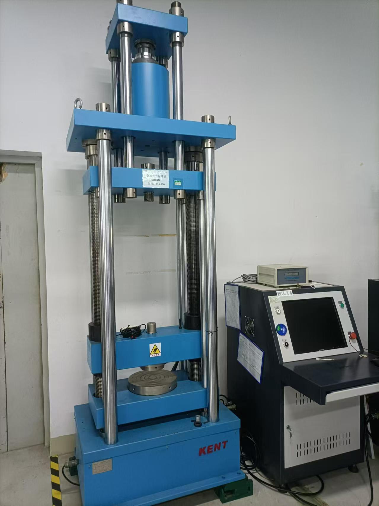
300kN superimposed force standard machine
Product Overview
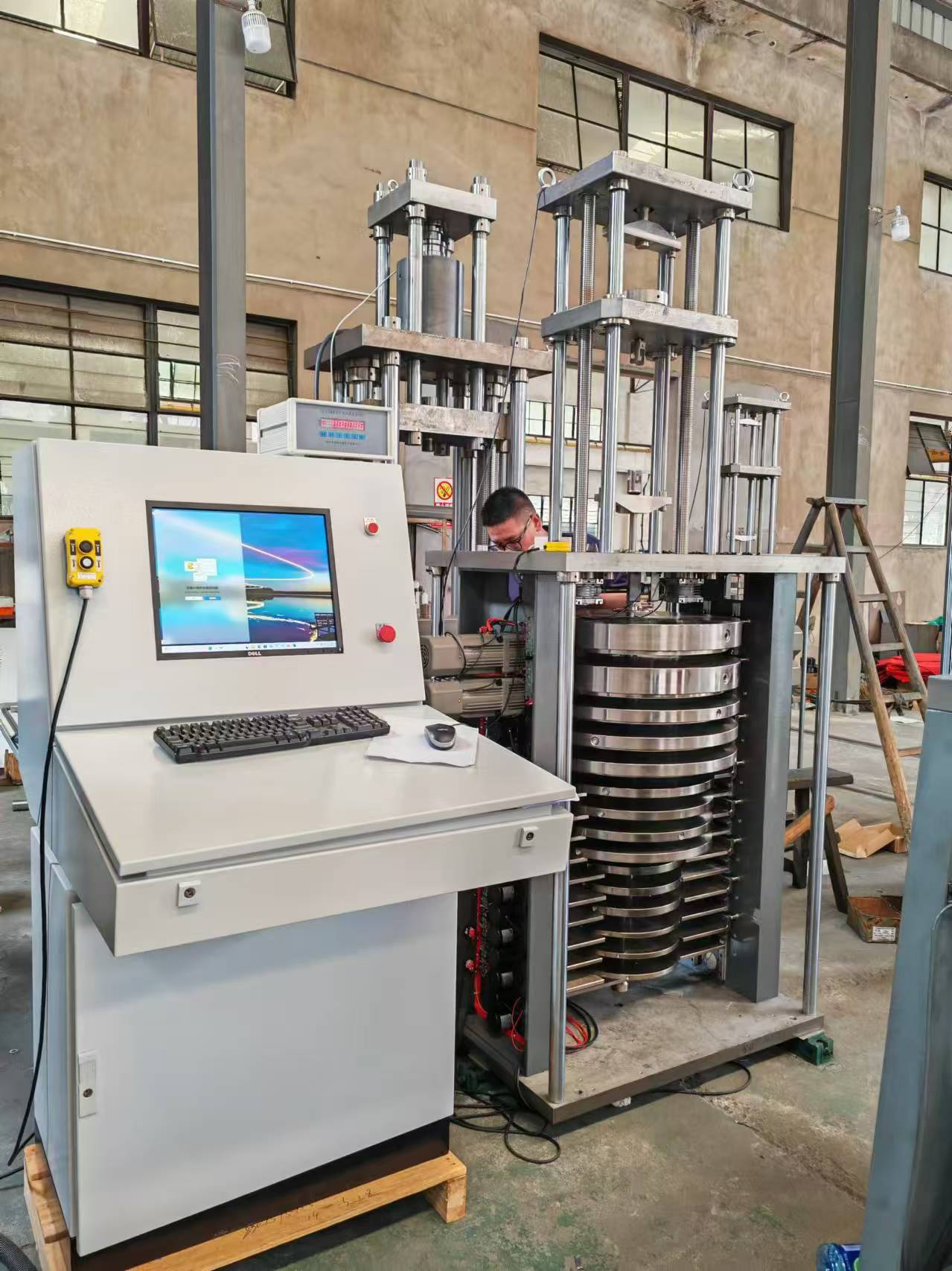
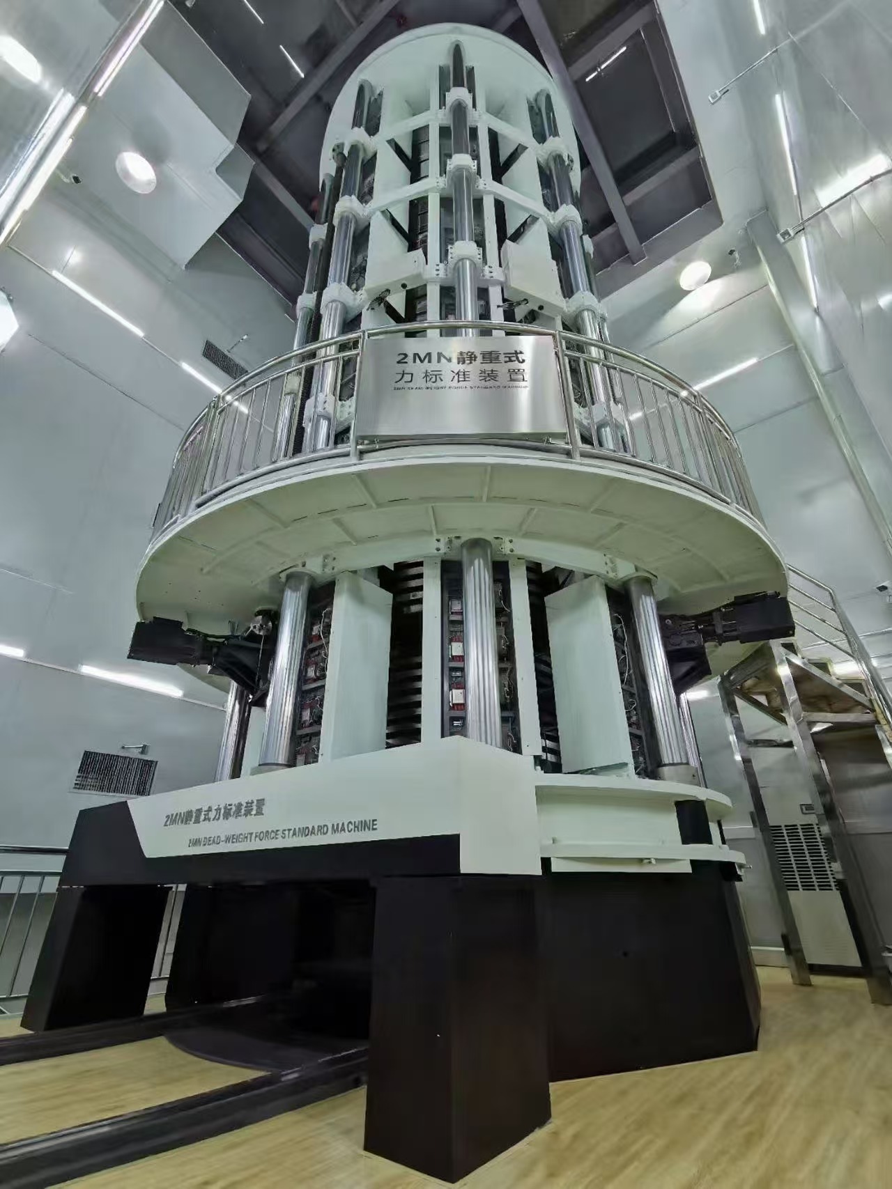
The stacked force standard machine equipment comprises a mainframe, a numerical control servo hydraulic control system, a standard sensor assembly, a workbench, automatic control software, and a printer, among others.
The bidding equipment fully meets the requirements of the Verification Regulation for Force Transducers (JJG391-2009), the Verification Regulation for Load Cells (JJG669-2003), the Verification Regulation for Working Force Measuring Instruments (JJG455-2000), and the Verification Regulation for Standard Force Measuring Instruments (JJG144-2007), enabling the testing, calibration, and verification of sensors.
1.Technical specifications and parameters
2.Detailed technical description
2.1. Host framework
2.2Numerical control servo hydraulic control system
The CNC servo hydraulic control system employs dual-pump CNC servo differential control technology, which involves "two servo motors controlling two oil pumps to form two sets of servo drive units, which in turn control the oil inlet and return of the hydraulic cylinders. The sizes of the oil inlet and return of the two sets of servo drive units are dynamically adjusted to achieve high-precision control.".
Controlled flow rate: 0~2000 ml/min
Control pressure: 0~25Mpa
Force source control fluctuation: <0.5/10-5
2.2.1Control principle
In an ideal state, the servo motor directly drives the oil pump. The speed and torque of the servo motor, as well as the pressure and flow required by the actuator, satisfy the following relationship through derivation:
P=p×Q (1)
Q=n×q (2)
From equations (1) and (2), we can obtain
P= p×n×q (3)
Due to:
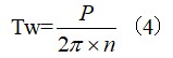
Substitute formula (3) into formula (4) to obtain
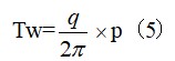
In the formula, P represents the system power (W)
p - system pressure (Pa)
Q - Flow rate (m3/s)
Tw - torque (N·m)
n - Motor speed (r/s)
q - oil pump displacement (m3/r)
According to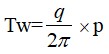 , it is a constant in an ideal system
 , so the torque of the servo motor is proportional to the pressure required by the system. According to Q=n×q, it can be seen that the speed of the servo motor is proportional to the required flow rate of the system.
From this, it can be deduced that as long as the torque and speed of the servo motor are dynamically adjusted, the pressure and flow required by the actuator can be provided. This is the basic principle of this control system.
2.2.2Problems that will be faced in practical applications:
a) Oil cylinder:
In practical applications, hydraulic cylinders all exhibit varying degrees of leakage, which is uncertain. The magnitude of the leakage varies greatly depending on system pressure and temperature, and it is nonlinear.
b) Oil pump characteristics:
Every oil pump has a working range. Below this range, the output of the oil pump increases nonlinearly, and the pulsation of the oil pump becomes very large, which will lead to instability in the hydraulic system.
c) Servo motor:
Currently, servo motors produced both domestically and internationally exhibit certain limitations in terms of stability when operating at very low speeds, but they perform very smoothly at higher speeds.
2.2.3 Solution:
Based on the aforementioned theory and analysis, the differential method is employed to enable two servo motors to control two oil pumps respectively, which in turn control the inlet and return oil of the cylinder. The increase or decrease in cylinder pressure is determined by the speed difference between the two oil pumps. Theoretically, adopting this solution can address the following issues:
Every oil pump has a working range. Below this range, the output of the oil pump increases nonlinearly, and the pulsation of the oil pump becomes very large. This will lead to instability in the hydraulic system, which is determined by the structure and characteristics of the oil pump.
For example, in a 500kN hydraulic power unit, an external gear pump with a displacement of 1.0ml/r and 100 gear teeth is used. Under ideal conditions, the minimum oil output resolution of one gear pump is 1.0ml/100=0.01ml.
Based on the experiment, at the 20kN force measurement point, the average rotational speed is 3.1r/min. This means that the oil supply requirement from the cylinder to the pump is: 1.0ml/r * 3.1 r/min = 3.1 ml/min. The control speed adopted is 100Hz (adjustment 100 times per second), which translates to 60*100=6000 times/min. This necessitates a minimum flow rate resolution of: 3.1/6000=0.00052ml. Evidently, it is challenging to meet such high-precision control requirements with a single pump.
For this purpose, two servo motors are used to control two oil pumps respectively, which in turn control the oil inlet and return of the cylinder. The difference in rotational speed between the two oil pumps multiplied by the displacement of the oil pump equals the oil supply volume of the oil pump to the cylinder. In terms of control, the rotational speed of the return oil pump is set to 300 r/min. Thus, at the 20kN force measurement point, the rotational speed of the oil inlet pump is theoretically 303.1 r/min. Although the oil supply volume of the two oil pumps to the cylinder remains at 3.1 ml/min in this state, with the oil pump rotational speed at 300 r/min, the minimum division after superimposing the flow rates of the two oil pumps is: 3.1/100/300=0.00001 ml. This fully meets the minimum division requirement of 0.00052 ml for flow rate.
Since the two servo motors operate at a speed of around 300 r/min, they can run very smoothly.
Due to the presence of an oil pump controlling the return oil, after the oil cylinder is treated with methods such as using sealing rings, its leakage is much slower than the return oil speed of the pump. Furthermore, this leakage can be resolved by reducing the return oil speed of the pump, which effectively creates an environment with relatively constant leakage.
In summary, using two servo motors to control two oil pumps, and the two oil pumps to control the inlet and return oil of the cylinder, can solve the problem:
a) Subdivide the flow rate of the hydraulic power source according to the control requirements to improve resolution.
b) Ensure that both the servo motor and the oil pump operate within their ideal operating ranges.
Control the uncertain leakage of the oil cylinder to a relatively constant level, ensuring precision in force source control.
2.2.4 Control principle:
The computer sets the standard force value according to the detection points (which can be multiple) required by the sensor under test . After starting the test, the computer collects the actual signal of the standard sensor through the standard sensor instrument , and sends speed and torque commands to the servo controller through computation. Servo controller 1 controls the speed and torque of oil pump 1 , and supplies oil to the cylinder through the directional valve . Servo controller 2 controls the servo motor 2 to control the speed and torque of oil pump 2 , and returns oil to the cylinder through the directional valve . The difference in speed between oil pump 1 and oil pump 2 determines the advance and retreat, pressure, and speed of the cylinder .
The hydraulic cylinder sends real-time signals to the computer through the standard sensor instrument and standard sensor . The computer sends speed and torque commands to servo controller 1 and servo controller 2 in real-time through computation, forming a closed-loop control. Until the force value of the standard sensor reaches the set force value, the measured instrument collects the signal value of the measured sensor at the set force value.
If there are multiple points to be detected, proceed to the next point and complete the detection one by one.
2.2.5 Component function
a) Computer and control software
Equipped with working software in the Windows environment, it performs standard machine human-machine dialogue, controls parameter calculations, and handles test data acquisition, processing, storage, and screen display functions. The reserved ports provide LAN sharing and processing capabilities for test data.
b) standard instrument
Collect signals from sensors of the force standard machine under different force conditions and provide them to the computer for computer control and test data acquisition. The parameters are 24-bit AD and 7.5-bit resolution.
c) Servo motor and controller:
According to the instructions of the computer, provide a certain speed and torque to the servo oil pump.
d) Servo oil pump:
Based on the speed and torque of the servo motor, a certain pressure and flow rate are provided to the cylinder.
e) Electromagnetic directional valve:
Control the lifting and lowering of the hydraulic cylinder.
f) Overflow valve:
Overload protection, controlling the maximum pressure of the hydraulic cylinder and servo oil pump.
2.2.6 Main configuration:
3. Electrical control system
3.1 Data acquisition unit
The data acquisition unit consists of a high-precision controller, RS232, RS485 interfaces, etc.
The high-precision controller is the core component of the data acquisition unit: the self-developed CLY-2008-1 high-precision acquisition instrument, with a capacity of 600,000 codes and the ability to expand up to 12 channels, is used to acquire the output signals of the verified sensors and transmit them to the control computer for data processing.
3.2 Data processing unit
The data processing unit consists of a control computer and a printer.
For ease of operation, the control computer is chosen from well-known domestic brands such as Lenovo commercial computers or industrial control computers. The computer communicates with high-precision control instruments and sensors through interfaces such as RS232 and RS485 to process data transmitted by the data acquisition unit. It performs data processing according to the requirements of the verification procedure and generates calibration or verification data documents.
To ensure system security and prevent issues such as computer virus intrusion from damaging the system, computers must be used exclusively for their designated purposes and not for any other purposes.
The printer is used for data printing or certificate printing, and an HP laser printer is selected.
3.3 Software component
The role of system software is to cooperate with relevant hardware to achieve sensor calibration or verification.
3.3.1 Working principle
It is generally used for verifying or calibrating sensors. The "inverse effect" caused by force fluctuations at the force measurement point can affect detection accuracy. A set of computer program algorithms is developed through mathematical methods to achieve rapid and high-precision positioning, and fast control software is also developed.
Multi-level exponential decay was adopted, but its adaptability was not strong, and there were significant differences among various machines. Therefore, the dynamic control frequency was increased (≥100Hz), greatly enhancing adaptability. To improve the control effect, a variable parameter table was established using mathematical methods, enabling rapid and error-free positioning. The above methods were formulated into a complete set of computer program algorithms using mathematical methods to achieve rapid and high-precision positioning.
3.3.2 Main Functions
Software design and development for programmable controllers, specifically the rapid-running software programs developed, primarily serve the following functions:
a) Fully complying with the requirements for testing stipulated in standards and regulations such as "JJG1116-2015 Verification Regulation for Force Standard Machines", "JJG144-2007 Verification Regulation for Standard Force Measuring Instruments", "JJG391-2009 Verification Regulation for Force Transducers", and "JJG 669-2003 Verification Regulation for Load Cells", the software has been developed to enable automatic data acquisition and processing.
b) The system software automatically generates original records and certificates, and prints verification results in accordance with national verification procedures, production process specifications, and management requirements.
c) It facilitates the input of various information required for verification and has a memory function for information that does not change frequently (such as standard parameters).
d) Complete, flexible, and convenient online documentation allows users to quickly access help when encountering issues during software usage by clicking the "Help" button.
e) Multi-unit conversion function: kg, t, N, kN, lbs, etc. can be converted to each other.
f) The relevant parameters of the verification, calibration, and testing processes can be visually and intuitively displayed on a computer.
g) Multiple protections: maximum signal protection for standard sensors, overload protection for the range of the verified sensor, and hydraulic overload protection.
h) It has good fault tolerance and provides timely prompts for abnormal situations that occur during the verification process.
i) Ensure data security, and test data must not be altered.
j) It features password protection, including a separate administrator management interface.
k)It features a flexible query function, allowing users to search historical records based on information such as calibration date and sensor number.
For the Microsoft XP operating system software platform, we utilize VC combined with the MFC class library of VB to provide object-oriented programming capabilities. The development interface is based on a single-document format, which is concise and clear. We employ threads for serial communication, avoiding the situation where the program crashes due to serial communication wiring failures.
In the system, various parts that need to be monitored are displayed on the interface using graphical elements (icons) with similar shapes, thus forming an animated model on the computer screen that can visually, vividly, and comprehensively express the mechanical structure of the equipment. Software technology is used to integrate bidirectional information between the control computer and the monitored equipment, display the operating status in real time, automatically draw loading curves according to the working steps, and establish a connection between the working components of the equipment that need to be monitored and the animated components on the screen, achieving the function of representing the working status in the form of animation and issuing control instructions by clicking on the animated components with the mouse.
In addition to automatic operation, it can also achieve intuitive and simple operation, as well as visualize the execution process. After the experiment is completed, it can automatically calculate and output the data processing results.
1) work software
Equipped with working software in the Windows environment, it performs standard machine-human interaction, controls parameter calculations, and handles the acquisition, processing, storage, and on-screen display of experimental data. The reserved ports provide LAN sharing and processing capabilities for experimental data.
2) Multi-channel control software
Equipped with 5 channels, it can record 5 standard sensor parameters, meeting the metrological needs of multiple standard sources and multiple measurement ranges with one device.
3) Multiple force units can be switched at any time
Units such as kilonewtons, kilograms, tons, and pounds can be freely switched at any time to meet the needs of different force units.
4) Multiple gravity value overload protection function
Hardware protection:
- Limit protection for moving parts such as hydraulic cylinders and moving beams
- Maximum pressure protection of overflow valve system
- The emergency stop button manually cuts off the power supply in case of an emergency
Software protection:
- Maximum signal protection for standard sensors
- Overload protection for the measured sensor range
- Servo drive operation status protection
If you are interested in our products, please fill in the message below to contact us and get a quote!
We will get back to you as soon as possible!
Type What You are Looking for